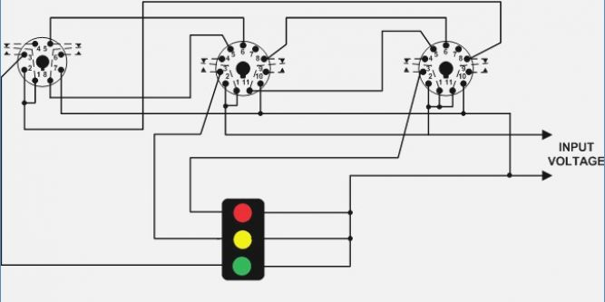
8 Pin Wiring Diagram. An additional wire referred to as 'Power Good' is used to prevent digital circuitry operation during the initial milliseconds of power supply turn-on, where output voltages and currents are rising but not yet sufficient or stable for proper device operation. These diagrams are for the use of professional installers.

It may transfer power better hence the connector is suggested for higher-level electric in the auto.
An additional wire referred to as 'Power Good' is used to prevent digital circuitry operation during the initial milliseconds of power supply turn-on, where output voltages and currents are rising but not yet sufficient or stable for proper device operation.
Dayton Time Delay Relay Wiring Diagram Download | Wiring ...
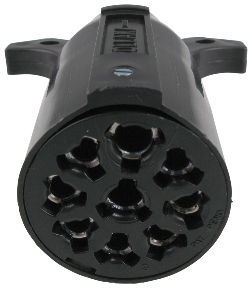
ford 7 pin round trailer plug wiring diagram round pin

MerCruiser 496 8.1L Mechanical Engine 14 Pin Connector ...

תוצאת תמונה עבור wiring diagram for semi plug | Caravan ...

8 Pin Relay Wiring Diagram - Wiring Diagram And Schematic ...

Item # 750XBXH-120A, 750H Hermetic Octal Relays, 8 Pin ...
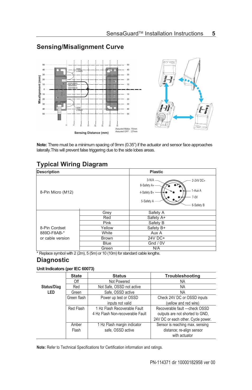
Sensing/misalignment curve typical wiring diagram ...
Garmin 8 Pin Transducer Wiring Diagram
8 Pin Ice Cube Relay Wiring Diagram
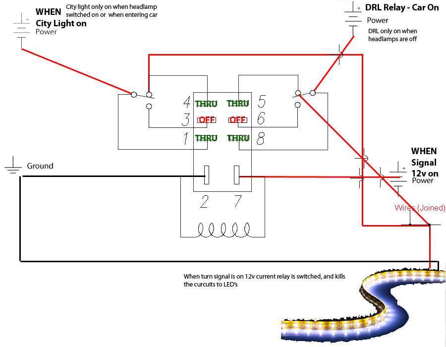
As you can see from the diagram above, we are now using two Arduino digital I/O pins. Microphone Wiring Diagrams pop - Some mic wiring diagrams for Ranger, Realistic Alan, Cobra, Ge, Uniden, Yaesu, kenwood, Icom radios. I've attached an image of the wiring according to the diagram you linked with the yellow and black colour.


0 comments